Page 2
Winch
The Australian ADF UL1700L version uses the Werner & Co winch. Name plate data interpretation: breaking force 21,404 kg and Tractive force 6403 kg. It is designed for 14mm steel cable.
Control knobs on the winch:
- Passenger side knob engages gearbox or allows free wheeling in order to drag cable out by hand. Pull out the knob to disengage winch. WARNING: It is not suited as an emergency disconnect, because once the cable is under tension, you will not be able to pull it out.
- Drivers side knob is a friction adjustment. Wind it in for friction to slow the drum when paying out cable by hand. Loosen when winding in the winch.
It is best to remove the winch completely, to work on it. The winch is held on by 2 large pins (see photo below). Don't forget to check the winch gearbox oil.
Drive Chain
When I opened the drive chain case (on drivers side), the chain had some surface rust mixed with grease (nothing of consequence however). A large 'O' ring is used to seal the side casing but obviously not intended to be a watertight seal on the rough casting. The chain operates a cable indexing slider to ensure cable winds evenly across drum. A gear puller is required to remove the large RH cog. After cleaning, I painted the inside, lithium sprayed the chain, applied sealant to the 'O' ring and installed a drain plug in the base of the case (as its likely to get more water in it over time).
Coupling
The connection between the rear of the winch and the vehicle PTO shaft, includes a torque overload clutch feature. The photo below shows the 4 ball bearings used in the overload clutch. I cleaned it up, greased, repainted and resealed the cover. Note: They are supposed to be adjusted on a regular basis if used a lot. Mine has never been used since refurbishment.
Bolts:
There are four M16 high tensile grade 10.9 main bolts holding the winch brackets in place. Unfortunately, as the front of the chassis box channel is open to the elements, and crud enters, and when wet, the mud starts to corrode the bolts that are threaded into the hollow chassis. The risk with removing bolts that have lain undisturbed for eons, is that you can strip them or shear them off. As shown in the first photo below, they were corroded and no longer fit for service. This is the likely condition of these bolts for all of these vehicles of similar age, and I consider it a mandatory check if the winch is going to see any service.
Rope
I looked at synthetic, i.e. Ultra High Modulus Polyethylene (UHMWPE).
Dyneema is one of many well known brand names for UHMWPE. It is available pre-terminated or you splice an eye (soft or hard) on it yourself. Note: The open teardrop eye is designed for steel cable, whereas the closed donut eye is used for synthetic ropes. The reason: the teardrop open ends can cut away at the rope and fray it.
Grades: SK99 has 20% strength advantage over SK78 and crucially retains the same elongation and creep characteristics as SK78 – out-gunning SK90 on all levels! SK99 has an unmatched strength to weight ratio. SK90 and 99 is expensive and as I am always looking for best value for money, I went for the middle of the price and performance range: SK78. However, if you expect to do lots of winching, one might wish to consider SK99?
Advantages of UHMWPE:
- Will float on water
- Can be easily cleaned.
- Depending on the grade, it can be stronger than steel for the same diameter.
- Excellent fatigue resistance (cyclic bending).
- Excellent UV and chemical resistance.
- Good abrasion resistance.
- Depending on grade, no snap back risk.
- But most of all, Can be slice jointed and re-terminated in the field by hand
Negatives for UHMWPE:
- Exhibits creep, i.e. elongation over time. Creep can often have a negative effect on a rope’s performance and strength when ropes are subjected to high loads for extended periods.
- Can melt at relatively low temperatures (140○C), so don't let the drum get too hot.
- Susceptible to cuts, it’s not uncommon to have to smooth the drum or fairlead, will likely need an abrasion sleeve. I only have heatshrink, and that might have to do?
1) Synthetic rope is NOT suited to the Werner winch supplied with some ADF Unimogs. The winch drum is designed only for steel cable. The drum has guide flutes along it at the exact spacing and size of the 14mm cable. These will cut into the synthetic rope if the rope does not sit in each groove neatly. As the rope is thicker than the steel cable when not under tension, it will eventually ride up over the sharp edges of the flutes and eventually be damaged. It will also not lay onto the drum evenly as the indexer operates at a rate to suit the thinner steel cable. Good chance it will all bunch up at one end, potentially resulting in jamming.
2) This winch is not meant to be operated without someone at the controls inside the cab. Once the cable is under some tension, the knob on the side of the winch cannot be pulled out. At least 2 people are needed to operate the winch safely. One inside the cabin at the controls, and at least one outside checking that the cable is winding onto the drum evenly. Also ideally, have someone else to watch the overall winching activity.
The maintenance manual recommends to be unwound and treated (grease) on a regular basis to prevent everything rusting up. I use Lanotec.
My cable weighs 26kg. To get it on to the drum: turn the drum by hand until the indexer is fully at the (passenger) side. There is a wedge shaped hole in the drum. Poke the cable through from the small side of the hole in the drum, drop in the wedge, tap the wedge down firmly (jamming the steel rope) to lock the cable in sufficiently for the cable to wind onto the drum properly. Mark the cable with paint at about 6 turns or more (limit of unwind).
Headlights
On opening the origional headlights, one headlight was well sealed, and in good condition, the other had a leaky housing and there was corrosion.
LED headlights need to be ECE approved and within the norms of the existing standards. The key take away, is that LED lights need to be self levelling (adaptive headlights). Adaptive headlights require sensors, computers and servos etc.
After all this, I considered that its just too hard to comply with the very chaotic regulations with no conformity across the country. LED lights also emit a pure spectrum and its very difficult to equate colour and intensity to traditional incandescent light standards.
I ended up refurbishing the alloy casings painting inside and out, installing higher rated incandescent bulbsand replaced one of the Hella reflectors.
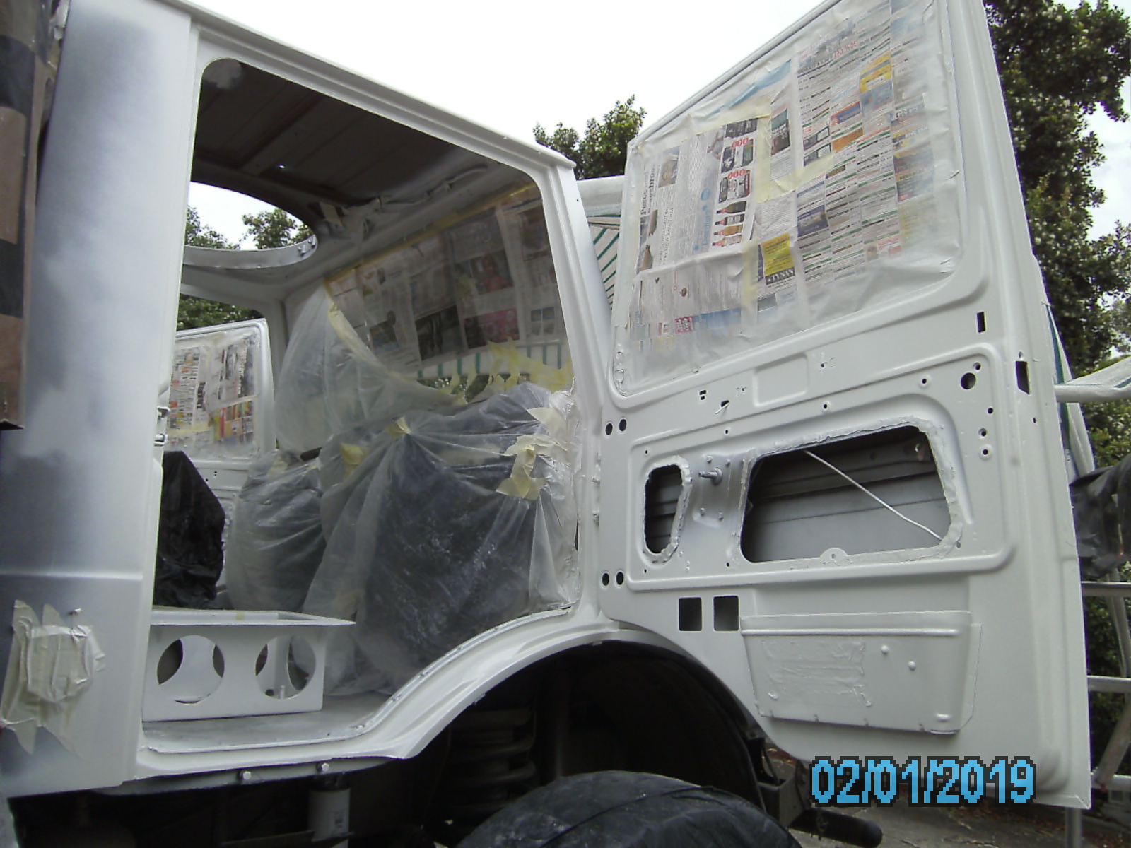
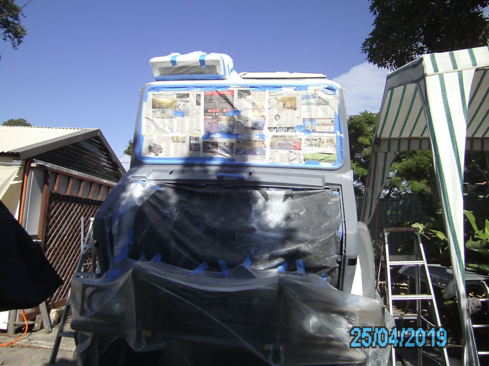
Painting the Cab
Interior
- Cab had to be mostly stripped out to repaint.
- I've left the dash in place, which means that behind the dash will remain drab green (but few will see it).
- Inside door panels coated with rust proofing and sound proofing.
- Underside heavy coated with Crommelin water proofing sealer.
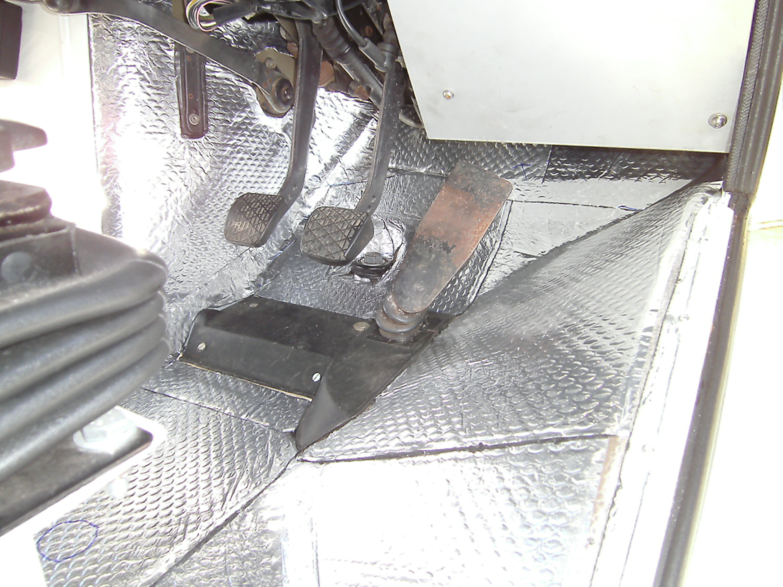
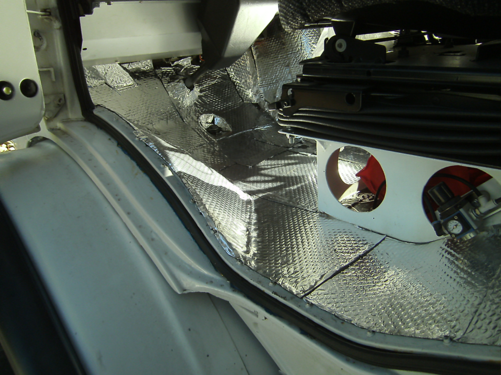
Sound Insulation
June 2021, got around to starting to install some sound proofing. So far, have installed only the butyl rubber sheets that have silver backing. The thick mass rubber sheeting is too thick at about 1/2 " and will take a lot of work to try and fix it down properly.
Interior Furnishings
The roof lining had to be remade.
Original seat belts were sent off to a Melbourne company to be re-terminated and parts replaced.
Lining door boards, door arm rests, sun visors, handles etc all re-stained black, so as to look new.
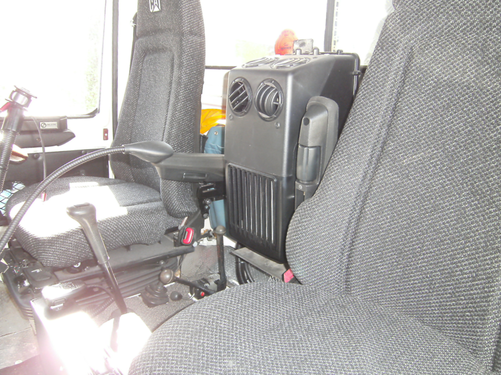
Cab HeaterFan
Dismantle the cab air blower system ducting and fan unit under the bonnet.
Good thing that I did open up the fan, as the fan blade was cracked in two places. I replaced the whole assembly with the newer improved design (see photo 4 below) with better air flow.
Cab Air-Conditioning
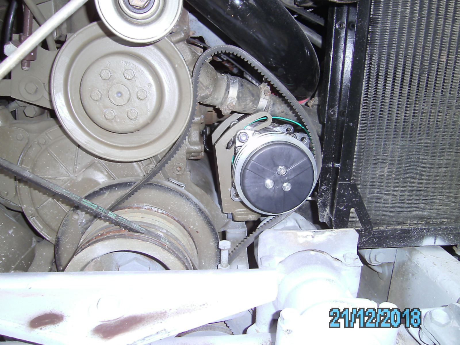
I've gone for cooling only (not reverse cycle), because the vehicle already has a hot water heater system. I installed the compressor up higher than typical. The advantage of it here (rather than just above the bash plate) is that it is unlikely to get immersed when river crossing. I fitted a heavy duty system to cater for the hot outback, but its too cold for me even for the hottest day. Components:
- wall mounted Red Dot Evaporator R6840024P
- roof mounted Red Dot Condenser R6160024P
- Sanden 9 piston Compressor (located in front of the turbo in place of the fan belt idler tensioner pulley)
It's end of 2019, system now charged and working great.
Note: Unidan has a complete air conditioning kit available and their evaporator unit fits very nicely under the centre of the front dash console. Its priced quite reasonably, as I soon found out that buying my own parts ended up costing me just as much or more, (due to import freight costs). If I had my time around I would probably just buy Dans kit. My design does however allow me to keep the floor space in the middle of the cabin clear, for the dog to rest and to easily step from one side of the cab to the other.
Exhaust & Air Inlet
Turbo:
I replaced the turbo (just in case it had some unknown defect and for some peace of mind) for a rebuilt unit (like new). Last thing you want is turbo blades fragmenting.
Rather than drill the turbo or the exhaust manifold, to fit the exhaust gas temperature probe, I drilled and tapped the exhaust casting after the turbo. There is a flat spot on the casting perfect for this (see first photo with the probe gland fitting in place).


I recommend that, before starting up the engine with a new turbo, make sure that there is oil in it, and ceck with suppliers recommendations. I did the following:
- Changed engine oil and filters,
- Catch bowl under turbo drain,
- Before fitting oil inlet pressure pipe, fill top with new oil (should drip out the bottom),
- Fit oil inlet pressure line (with new gasket and copper washers),
- Start engine at idle (do not rev) turn off after about 5 seconds,
- Check oil is coming out of turbo drain,
- Fit drain fitting with new gasket and drain hose,
- Start engine at idle (do not rev). Leave to run and inspect for any leaks.
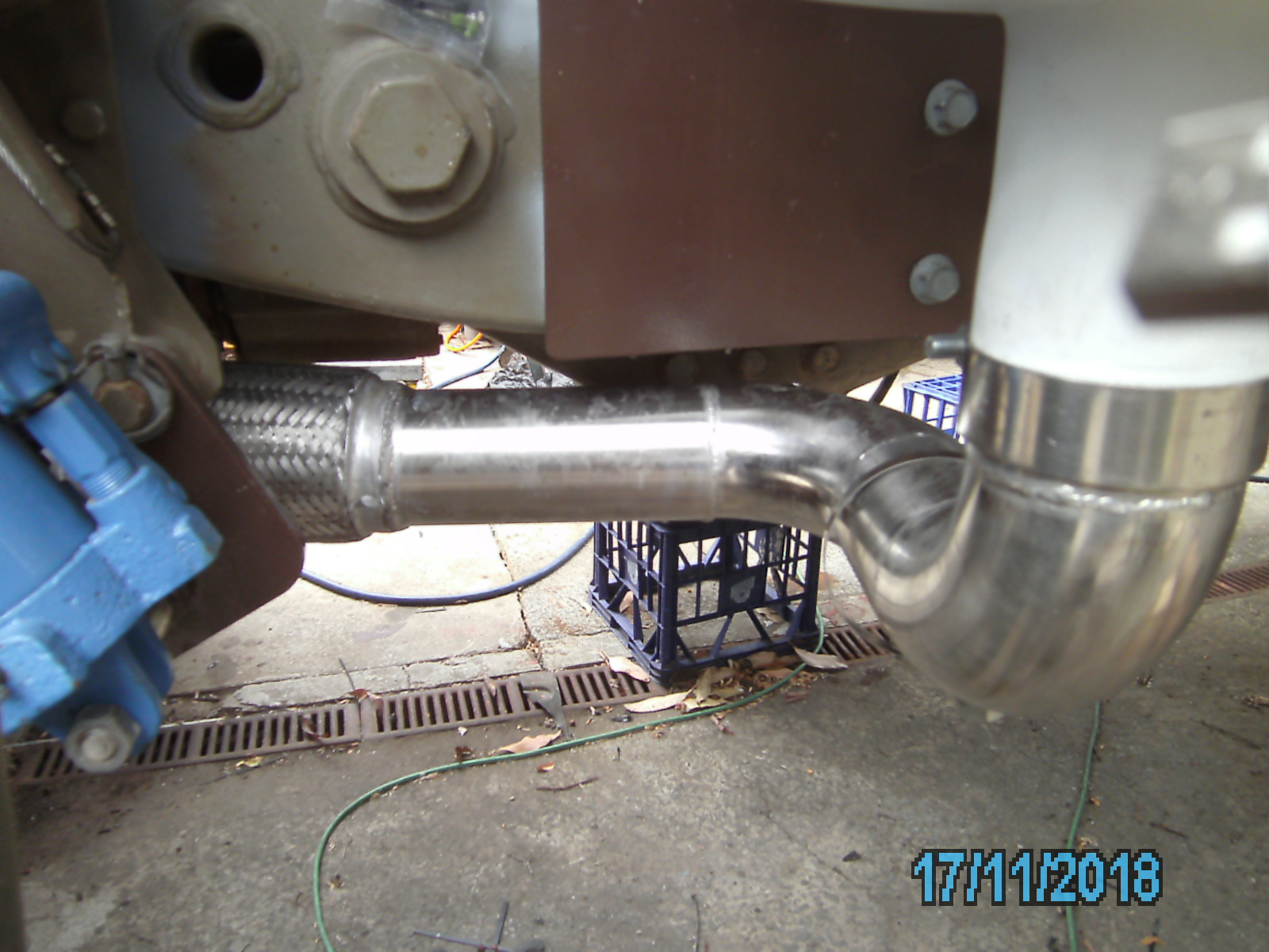
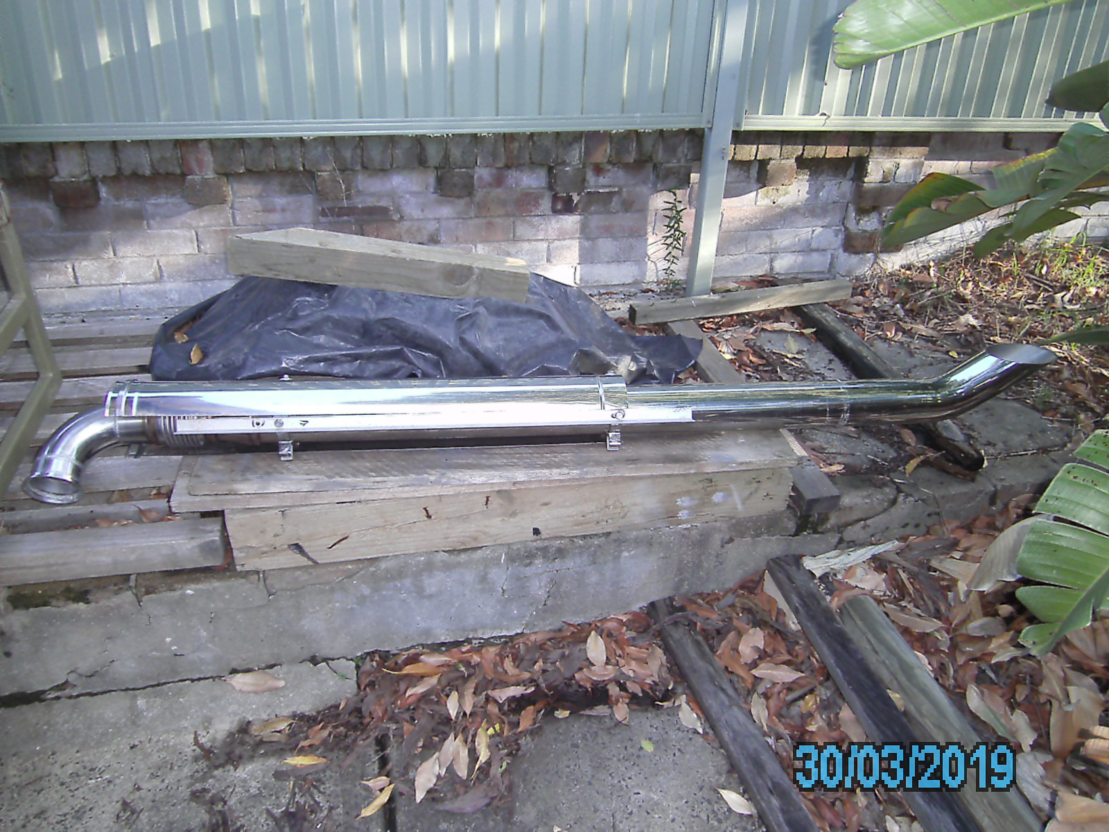
Exhaust Pipe.
I installed 3.5" stainless steel tube with thick wall elbows.
The flange however, had to be made to my drawing and I fitted an adaptor to go from 3" to 3.5". The gasket is part A302490008001 from MB.
Purging for TIG welding of stainless tube is essential otherwise oxide forms on the inside behind the welds. If purging is not done during welding, this oxide is a source of later corrosion, weakness and breaks up the gas flow (plus large dags which impede the gas flow).
I fitted a compact high flow low dBA Cowl muffler. Full welding of the stainless was done by Beauchamp Metals in Sydney Taren Point.
Intercooler
Fitted the Unidan standard intercooler Kit.
Exhaust Stack
Quite a bit of work in building fully stainless steel exhaust stack and sourcing parts.
Dec 2018. Decided that I needed to exhaust the smoke up and away, so I changed the arrangement from a low level outlet pointing downwards, to a smoke stack. I went for 4" polished stainless steel (4" is an odd size and difficult to find).
In order to allow flex between chassis and engine, a bellows fitting was required at the inlet to the muffler and on the outlet of the muffler.
Fuel Pump Settings
Minor horsepower increase is possible by adjustment to the Bosch mechanical fuel pump.
Linden Martin has provided useful details in Unimog Owners NSW Facebook site, on how to Un-Billycart an Ex ADF Mog Parts 1 and 2 (basically over-fueling).
I purchased a dozen used spare fuel injectors. I'm hoping that they only need a clean, spray pattern and pop off pressure check, if I need to replace the existing ones at any stage.
Air Horns
I fitted a pair of 82 class locomotive air horns underneath out of sight. These horns have the advantage of being robust and able to handle higher air pressure than most. They also tend to be very loud. I have them set up with a large bore solenoid (and isolation switch). If I quickly toot the normal electric horn only the electric horn makes a noise. If I hold down the button, everything comes on. This is because the electric horn responds very quickly, whereas the mass of the solenoid shuttle takes a little longer to move and for the air to compress at the air horn diaphragm. Hence by time I have removed my finger from the button for a quick toot, not enough air reaches the air horns to make a noise. I have reduced the sound level by fitting a smaller than usual solenoid.
Air Pre-Cleaners
I purchased two TopSpin plastic style pre-cleaners. They are not as strong as metal but have the big advantage of being lighter. It's unlikely that the cab air inlet snorkel pre-cleaner will be able to do much due to the much slower air speed, but its one way of carrying around a spare, just in case the engine inlet pre-cleaner gets knocked off on a low branch. These sort of pre-filters only come into their own in very dusty locations such as bull dust on outback roads, and the maker claims something like 90% dust extraction. This means that the main cartridge air filter under the bonnet will last much longer.

Tool Boxes,Handwash Water & Grey Water Tanks
I designed the (located front of rear wheel) heavy duty tool boxes mid July 2019. They were beautifully made (4mm marine aluminium), by Beauchamp Metals. Added a couple of poly rear water tanks (shown in black before painting) and a 300L poly watertank inside the large white storage box.
Battery Trays
The advantage of relocating to under the bonnet is that it means I can get rid of the existing ADF style battery box and fit my fuel tanks. The disadvantage however of this mounting arrangement, is that the batteries have to be prior removed before the air filter can be changed or the cab tilted.
Maintenance Manuals
There are three main sources that I use:
1) Under the ADF freedom of information act, I applied to obtain various additional maintenance information from the ADF, which they agreed, but rather than just provide it directto me (and I disseminate it), they arranged for AFM to make available the information on their web site. Its likely a good idea to download copies of manuals etc, in case their site closes one day.
2) Workshop Manual and Parts List. I use the free VM-Ware Player (virtual Windows XP Workstation) to run the applications. I purchased the following applications from 'emanualonline':
- Mercedes_2014_WSM (workshop manual) and
- Mercedes_2014_EPC (electronic parts catalogue).
Note that these two applications can be quite difficult to use. You will need to plug in your VIN i.e. WDB435 ...................... . After that you can select the category you are interested in. Unfortunately not all parts for the ADF Unimog versions are listed, but the far majority of standard parts are there.
3) Internet Forums:
- Mercedes Benz Forum
Canvas Covers
Found a good local upholsterer, who has the correct 'olive drab'military colour canvas at A L S Upholstery at 436 The Boulevarde, Kirrawee NSW 2232, Australia.
Crane for spare wheel
A small crane is required to lift the spare wheel up and down from the back of the tray. The best quality light-weight version is the Spitz-Lift, but expensive compared to some other heavier steel versions.
Towing
There are strict procedures for breakdown towing. For the ex ADF U1700, if towing by raising the front (with the rear end on the road), part of the gearbox will be spinning and it needs lubrication. The gearbox mechanical oil pump cannot work with the gearbox in neutral (its driven by the input shaft) . Therefore, I am advised by forum members that the gearbox will need to be in gear whilst towing. However, for the gearbox to be in forward or reverse, the engine will need to be disconnected from the gearbox, otherwise the engine will be spun via the driveshaft (risking damage to the engine and cause a dragging load on the tow vehicle). Apparently if towing forward, then the gear lever must be in forward. If towing backwards the gearlever must be in reverse (so that the oil pump rotates in the right direction).
The vehicle can only be towed (by raising one end) for up to 1km (with a speed restriction) without first removing/disconnecting the drive shaft (between clutch and gearbox). Refer to the specific requirements and restrictions for your vehicle before towing. On my vehicle, only the gearbox end need be disconnected providing that one can safely tie the loose end of the driveshaft up out of the way (maybe take some coat-hanger wire with you to do this). The driveshaft cover (M8 bolts) needs first removing in order to get to the gearbox end of the driveshaft flange. Some forum members claim that the tow truck drivers usually do this disconnection for you, but I'd make sure you can do it. If you cannot safely tow by lifting one end, a low loader may be required. Note: There are restrictions on overall height when the mog is on the rear of a low loader/tray, as well as time of day and route permits sometimes required.
Roof Lining
Roof lining board was warped, broken into pieces and badly water damaged and had to be remade.

Rear Tray Replacement Decking
The cargo style of vehicle has a plywood tray, with the last 1/3 covered with aluminium checkerplate. Its highly likely that there will be portions rotted on most vehicles of this vintage.
Thermo-lite Board was the best replacement product: Its expensive because the sheet sizes mean there is a fair bit of wastage but its the perfect strong no-rot material and at 19mm thick, its the perfect replacement thickness. Last 3 photos show it fitted to front half of tray frame. I used countersink stainless steel M8 bolts to secure it (using same existing mounting holes). CAUTION: Its packed with glass fibre, and you will need to wear a dusk mask against the dust when cutting/drilling it. The dust is very electrostatic, and will stick to everything in sight (including your clothes, your lungs and skin).
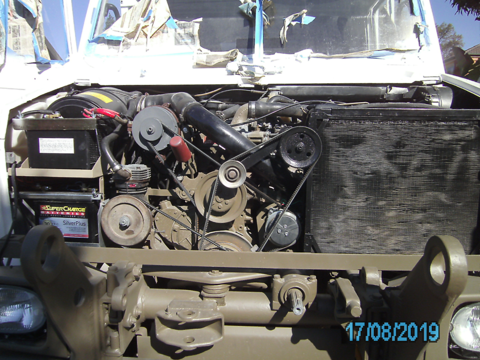
Engine Belts (AVX13 Notched Vee belt)
The below length belts are for my ADF Unimog. If you change for example: generator to alternator or add air conditioning compressor etc, then belts will be different. I have tried many different lengths, and here is what I ended up with:
- Air Pump 1335
- Steering Pump 950
- Fan Spindle Drive 1625
- Water Pump 1360
- Generator 1125
- Radiator Fan 1125
Some good brands are: Optibelt (Marathon X) and Gates (Green Stripe). Note that I have fitted some shorter than standard belts, in order to reduce belt slap and whilst difficult to get them on, they allow some decent tension to be achieved.
Cabin Mounts & Suspension
I was having oscillation problems initiated by undulations in the road at certain speeds.
Cabin Mounts: After much discussion, Ben Nash from MogCentral, mentioned a similar problem that he has diagnosed in the past: Worn cab mounts allowing the cabin to bounce and thus affect the accelerator linkages which are fixed to the cabin, thus starting an out of control oscillation with engine speed going up and down as the cab moves up and down. So I raised the cabin and inspected the rubber cab mounts.
Once I got the mounts out, there was lots of rust powder inside because nowhere for water to escape to. Nothing serious but the entire inside of the box section seems never to have been painted so I treated it all with fish oil inside. Note: I also treated all bolt threads with anti-seize before I insert them, just in case someone needs to access them again.
The rear were acceptable but the front were worn and were replaced, It resolved the oscillation issues.

The above photo shows where the rubber had come away from the metal. Both sides of both frontmounts were like this.
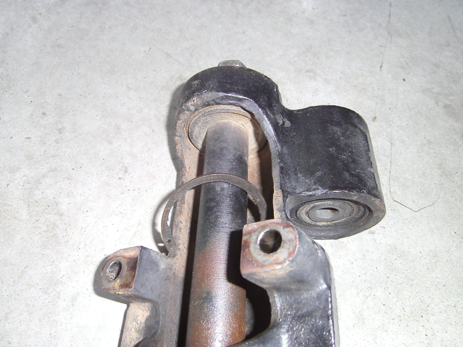
Shock Absorbers
I replaced the old shock absorbers with 'Iron Man' from Mog Central. Most of the 20mm bolts were difficult to remove.
A close up photo further below shows how the threaded profile of a bolt is typically worn down in the middle (see middle photo below) from the many miles of hammering from the shockies. Best to replace all bolts at the same time. I found every bolt, bar two (which were newer than the rest), had this wear deformation.
Fan Spindle belt tensioner
The belt tensioner was weak. As its a specialist job to pull out the spindle and change the rubber tensioner bush, so I had the bearings replaced at the same time. Bearings are quite common. I used SKF 62304-2RS1. The pulleys come off easy enough. Watch out for the small key in each end of the shaft, easy for them to fly out. The fan tensioner bush is very tight to remove or install. A strong press is required. Before you push out the original bush, measure how far the cogged face protrudes out of the casting, so that when you push the new one in, it goes in exactly the same distance as previous. I replaced the idler pulley (shown with yellow cap) at the front also (it was making a slight noise).